Sponsored links registered users of the site do. Registered users of the site do not see these ads.

Te 6522 Led Light Bar Relay Wiring Diagram On Denso 12v 4
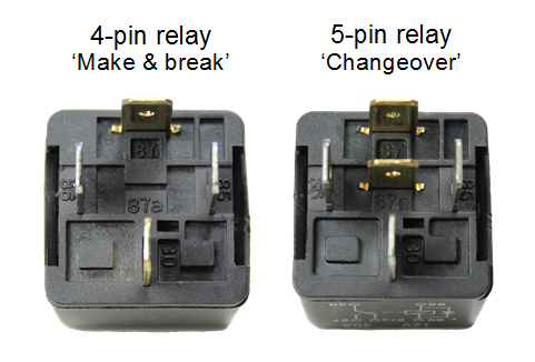
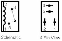
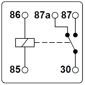
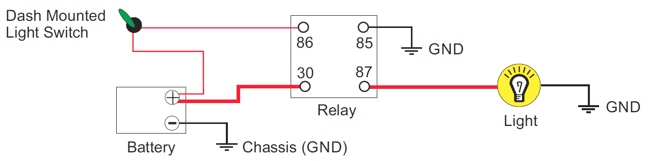
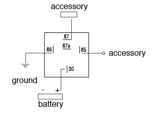
Denso 4 pin relay diagram. 3 4 1 2 rectange so which wire goes where. Wiring diagram for denso alternator 2017 wiring diagram hitachi. Multimeter used in video. An iso micro relay has the control circuit connected to pin 86 and pin 85 and the load circuit connected to pin 30 and pin 87 or 87a. Collection of denso alternator wiring schematic. The diagram on the relay is as follows.
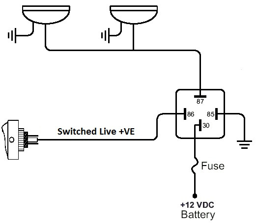
The iso defines this type of relay as 1 inch 25 cm by 1 inch 25 cm by 05 inches 254 mm by 254 mm by 127 mm. Methods for circuiting ups inverter with home office wiring. Not just what the diagram says but understanding what those pins need to see or be connected to. Batteries in series and parallel connections battery packs how to connect batteries in parallel with power inverter or ups wiring diagrams how to connect batteries in series with power inverter or ups wiring diagrams what causes battery terminals corrosion in car. Here is a video on how you can test a relay with or without a diagram. Relays are the integral component of any car wiring.
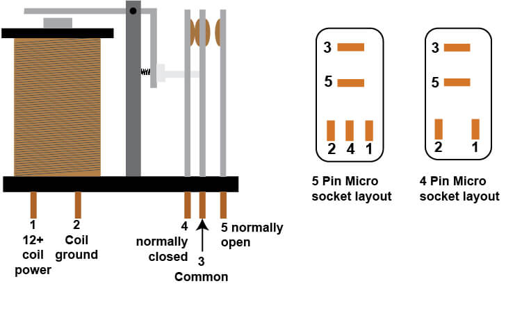
When a relay contact is closed there is a closed contact when the relay is not energized. How to super. The ems 4 doenst have a control like this by default but depending on your wanting or ability to test different things you might be able to come up with an acceptable way to control the alternator. Also when the relay is deactivated from activated state the common pin will conversely break away from contact with the no pin and return back in contact with the nc pin. Lost my diagram manual and need to wire up a relay for my blower motor. Determine that the relay is an iso micro type.
A wiring diagram is a simplified traditional pictorial depiction of an electrical circuit. September 3 2018 october 20 2018 by larry a. How to test a 3 4 or 5 pin relay with or without a diagram duration. No car wiring can be complete without these. Fr sounds like a 5v control output to the alternator and g is likely what the stock ecu is referencing to control the output. How to improve touchscreen sensitivity on android smartphones.
Wiring diagram for denso alternator awesome wiring diagram. Iii double pole single throw dpst such relay has 6 terminal pins which consist of a pair of coil pins and two pairs of pins where pins in each pair can be made connected or disconnected by activating or deactivating the relay. Denso relay 4 pin wiring diagram. I cover 34 and 5 pin relays and all you need is a 12v source a multimeter and a test light. Rocky x tv 20251 views. Relays are used to bypass signal wire and directly supply current from battery thus your car wiring remains safe from heating up and burning due to the load of heavy components.
It reveals the elements of the circuit as simplified. I will have a basic spst switch to trip the relay i have a denso 4 pole relay used for fuel pump window motors etc and i would just like to know which poles go to what. In either case applying electrical current to the contacts will change their state. Denso parts are often used in japanese assembled cars including cars manufactured by renowned brands like toyota honda mitsubishi suzuki mazda daihatsu and several others. Relays switches are used to open and close circuits electromechanically or electronically. How to wire a 4 pin relay 12 volt dc micro duration.
When a relay contact is open the relay is not energized. Free wiring diagram menu. Relays are generally used to switch smaller currents in a control circuit and do not. Denso alternator wiring schematic. Here we look at relay switch pin diagram and the different kinds of relay switches. How to stop and protect battery terminals from corrosion.
Denso relay 4 pin wiring diagram.
Gallery of Denso 4 Pin Relay Diagram