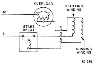
Terminal markings and internal wiring diagrams single phase and polyphase motors meeting nema standards see fig. Thermal contacts tb white m 1 z2 yellow z1 blue u2 black u1 red bridge l1 and l2 if speed controller sc is not required m 1 ln e white brown.
Mm300 Motor Protection System
Ge single phase motor wiring diagram. Single phase motor wiring diagram with capacitor baldor single phase motor wiring diagram with capacitor single phase fan motor wiring diagram with capacitor single phase motor connection diagram with capacitor every electrical arrangement is made up of various unique pieces. A wiring diagram is a streamlined conventional photographic representation of an electric circuit. Below are several of the top illustrations we get from different sources we wish these pictures will work to you and hopefully really appropriate to just what you want regarding the general electric motor wiring diagram is. Barely readable nameplate may say 5kc184ag201bu googling that model number suggests its a ge and the ag in the model number is probably wrong. Variety of ge motor starter wiring diagram. A wiring diagram is a streamlined standard pictorial depiction of an electrical circuit.
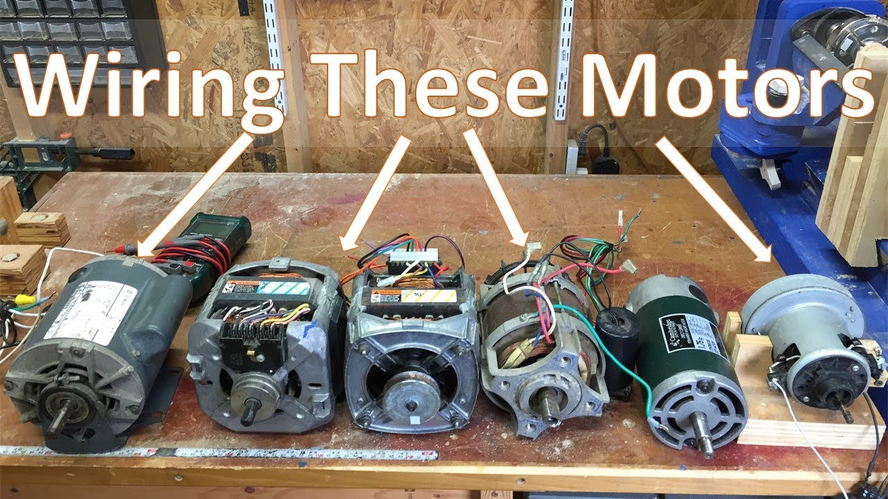
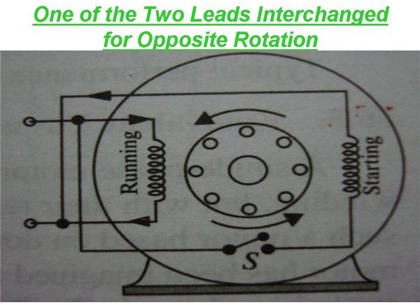
It is evident from the phasor diagram that the current through the starter winding is leads the voltage v by a small angle and the current through the main winding im lags the applied voltage. These instructions will probably be easy to comprehend and implement. General electric motors wiring diagram gooddy size. 800 x 600 px source. Assortment of ge single phase motor wiring diagram. I got an old motor missing the cover with the wiring diagram.
Exciting ge motor wiring diagram photos wiring schematic ufc204 size. Rotation cw frame size 48 shaft size 05 diameter x 423 long mounting stud mountable requires 10mfd 370v run capacitor. Each component ought to be placed and linked to different parts in particular manner. This is unlike a schematic layout where the arrangement of. With this particular manual you may be able to see how each element should be connected as well as the actual actions you need to take in order to effectively complete a. Carrier hc39ge226 14 hp single phase condenser motor fan single phase condenser motor fan includes.
It reveals the components. Ge motor starter wiring diagram sample. 800 x 600 px source. 2 11 in which vector 1 is 120 degrees in advance of vector 2 and the phase sequence is 1 2 3. It is to be. See mg 1 221 mg 1 224 direction of rotation.
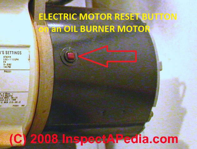
Posted on april 26 2018 august 9 2018 by headcontrolsystem. Furnas contactor wiring diagram download. Two speed motors for all other single phase wiring diagrams refer to the manufacturers data on the motor. Anyhow wired as received it starts and runs solo on 110 ok drawing 10 amps which is about half the 19595 fla on the nameplate for 110 v operation. Breathtaking ge motor starter wiring diagram contemporary and. Old ge single phase motor wiring diagram old ge single phase motor wiring diagram tmoose mechanical op 23 jun 11 0339.
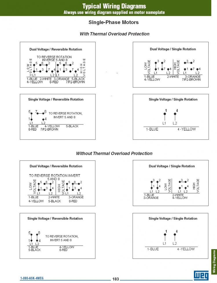
240 vac motor wiring wiring diagrams hubs single phase motor wiring diagram with capacitor. Thus a capacitor start induction run motor produces a better rotating magnetic field than the split phase motors. Wiring diagram ge dryer motor wiring diagram new m125r2002sepn. Dayton electric motors wiring diagram size. A wiring diagram usually gives details about the family member setting as well as plan of gadgets and terminals on the tools to help in structure or servicing the device. It is intended to help all the typical user in building a correct program.
Wiring diagram will come with numerous easy to follow wiring diagram directions. If not the arrangement wont work as it should be. 800 x 600 px source. It is important to point out from the phasor diagram that the phase difference between im and is is almost 80 degrees as against 30 degrees in a split phase induction motor. It shows the parts of the circuit as simplified forms and also the power as well as signal links in between the devices. Diagram dd6 diagram dd7 m 1 ln e diagram dd8 ln e l1 l2 l3 sc z1 u2 z2 u1 cap.
Gallery of Ge Single Phase Motor Wiring Diagram