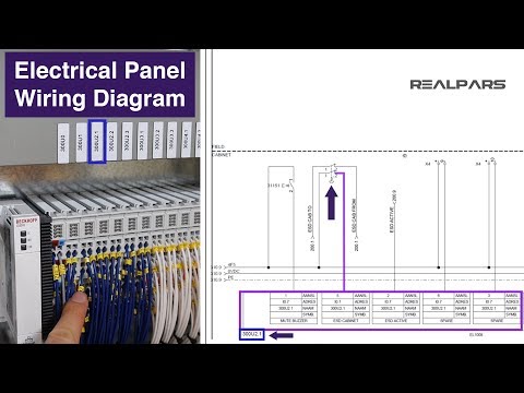
So this is how easy it is to read the wiring diagram for a control panel. The power supply is shown at the top and the earth at the bottom to facilitate understanding of the current flow.

How To Read Control Panel Wiring Diagrams
How to read control panel wiring diagrams pdf. This figure shows the e stop wired to cutoff power to all of the devices in the circuit including the plc. A diagram that uses lines to represent the wires and symbols to represent components. Figure 5 below shows a schematic diagram for a plc based motor control system similar to the previous motor control example. 2004 kia rio control panel wiring guide 15 pdf drive search and download pdf files for free. Basics 14 aov schematic with block included basics 15 wiring or connection. To understand how to read ladder wiring diagrams lets start with a simple electrical schematic consisting of a power supply switch and light then you will move on to our control panel sample wiring diagrams.
A diagram that represents the elements of a system using abstract graphic drawings or realistic pictures. Layout of the wiring diagram. Each of the wires in the wiring diagram. The cen tralrelay panel includes common power cir cuits such as battery power 30 ignition switched power 15 load reduction 75x and ground 31. When including a plc in the ladder diagram still remains. 5 things you need to know before designing your motor control center.
Whether its a simple home appliance or a control panel wiring diagram most systems and devices will include power supplies a ground and switches. All ground connections whether they occur as a splice. To begin understanding how to read and understand electrical circuit diagrams take our basic circuit and draw it out as it would physically be wired. Basics 13 valve limit switch legend. Wiring diagrams show the components of a system as well as their connections. So to sum it all up here is what we learned in this article.
The field device wiring diagram shows the location of each terminal strip in relation to where it actually exists within the device control house 12 the control hose wiring diagram shows connections made from field devices also using nomenclature control panel 131415. But it does tend to become more complex. Ground connections ground connections are represented as a line at the bottom of the wiring diagram page directly above the current track num bers. Basics 8 aov elementary block diagram. Centralrelay panel the centralrelay panel is indicated in gray at the top of the wiring diagram page. A 4 how to read the wiring diagrams how to read circuit diagrams how to read circuit diagrams the circuit of each system from fuse or fusible link to earth is shown.
It goes exactly the same for the other switches that we have here as well. Electrician circuit drawings and wiring diagrams youth explore trades skills 3 pictorial diagram. All the wiring that you see in the panel is done based on the wiring diagram. Each page of the wiring diagram shows the exact wiring for different sections of the control panel. Basics 9 416 kv pump schematic. Control panel diagrams however.
Basics 10 480 v pump schematic. Basics 11 mov schematic with block included basics 12 12 208 vac panel diagram. We show our ac power source on the left with l1 and n coming out of it our switch to the top and our light to the left. Basics 7 416 kv 3 line diagram. 2004 kia rio control panel wiring guide 2004 kia rio control panel warning indicator icons kia kia dealer as soon as possible to check your vehicle airbag warning light also known as electronic stability control esc the esp electronic stability program is an electronic system designed to assist the driver in maintaining vehicle control during adverse conditions esp checks where you are. This is what we draw using autocad electrical.
Gallery of How To Read Control Panel Wiring Diagrams Pdf