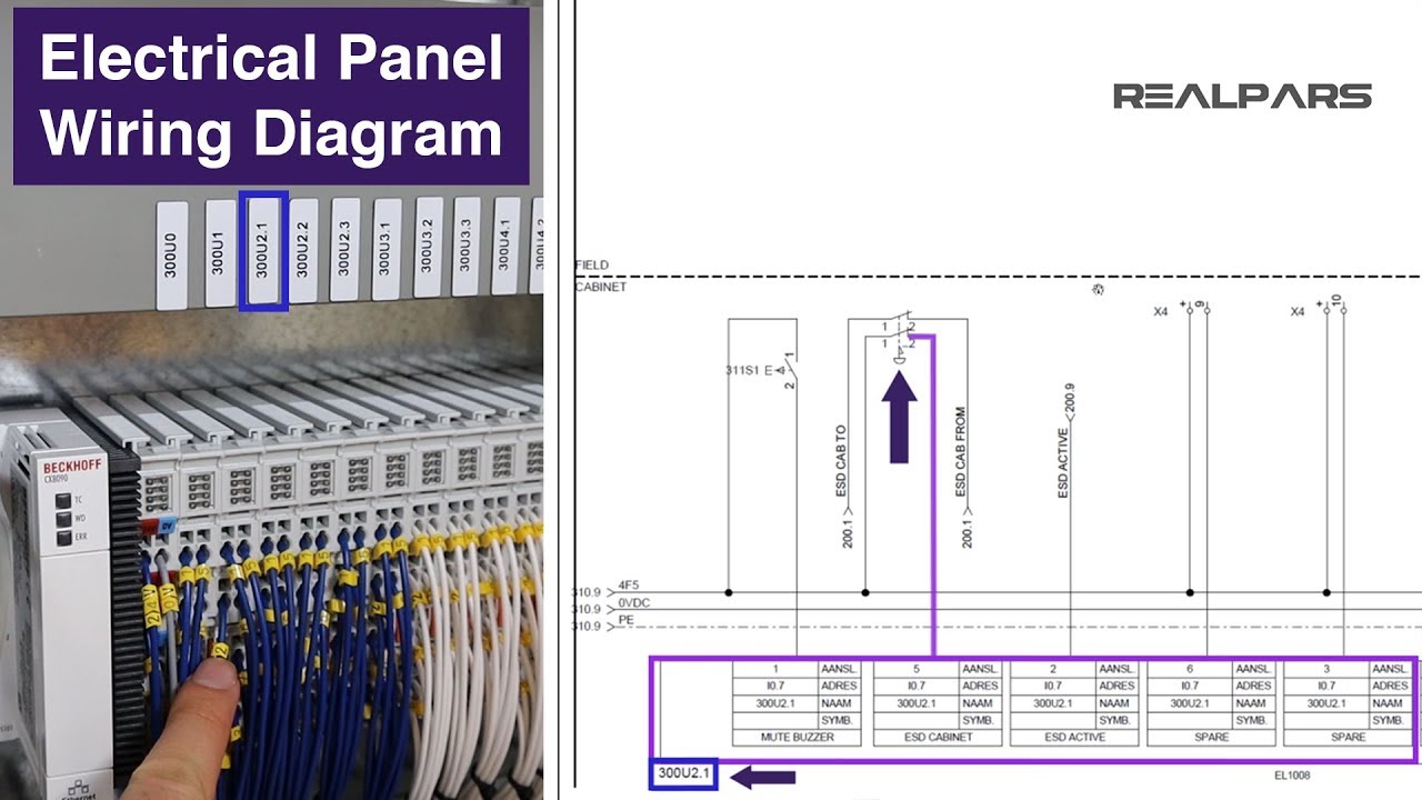
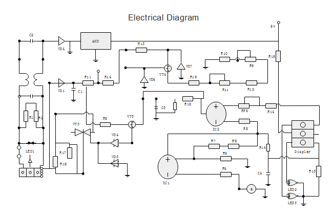
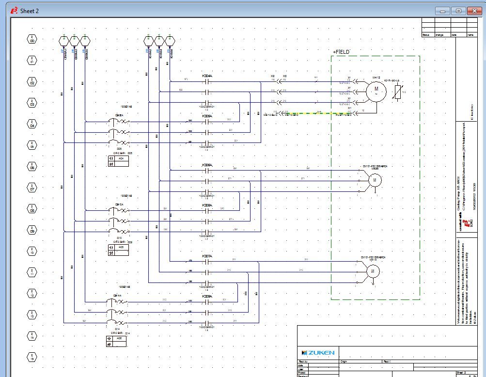
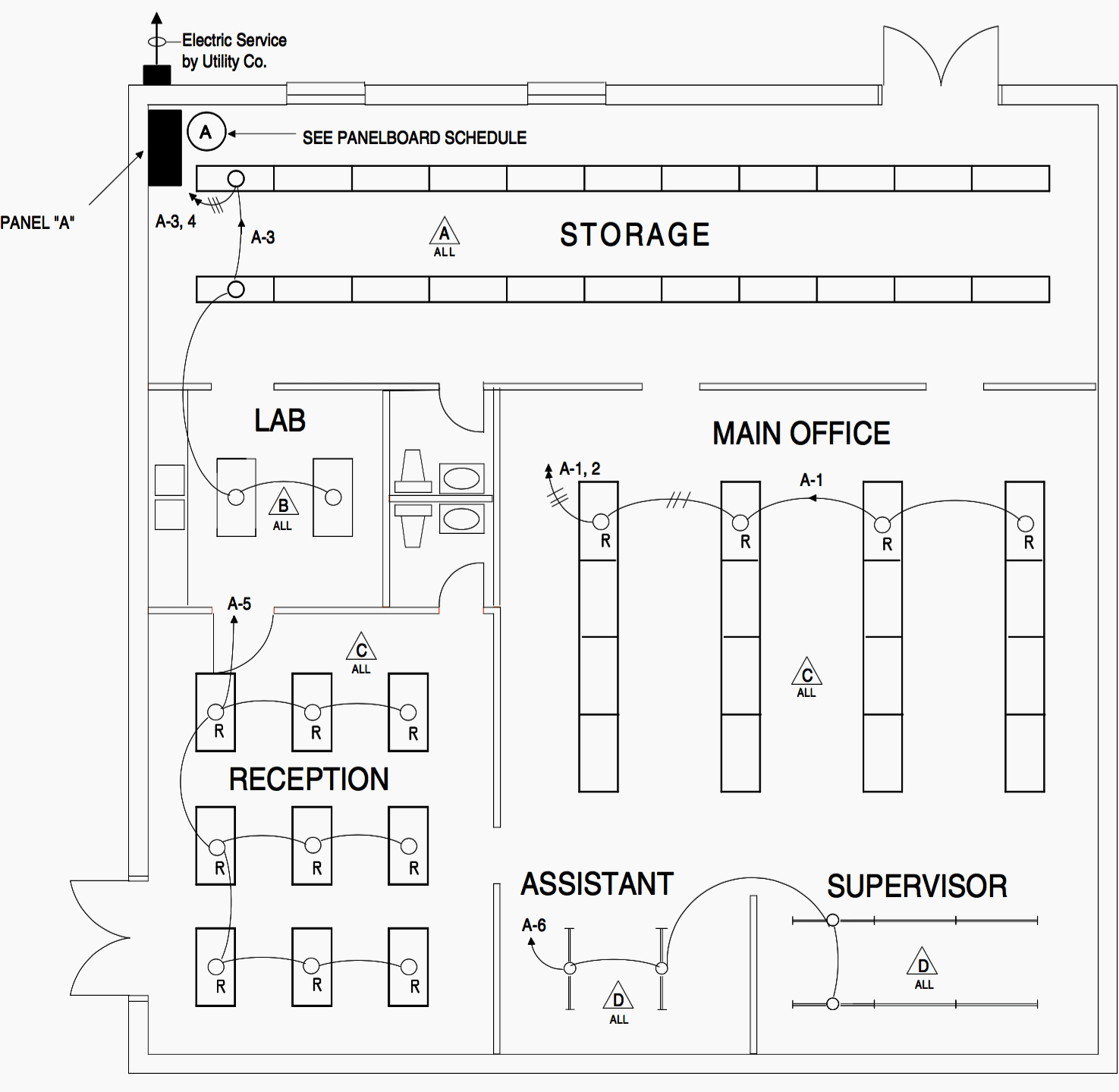
Industrial electrical wiring diagrams review is a very simple task. The numberletter code for each relay is carried by all associated.

Cat 6 Network Cable Diagram Reading Industrial Wiring
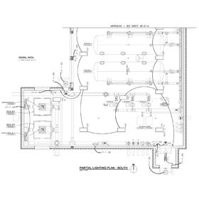
How to read industrial electrical schematics. Fuses or circuit breakers will cause power to fail if too much current is drawn. Electrical wiring diagrams of a plc panel. Think of reading schematics like a book would be read. Tips on reading industrial electrical schematics one of the easiest ways that things get misread is not identifying the schematic symbols used in the electrical. The course covers several types of industrial control prints for a variety of different motor driven processes with an emphasis on the differences between type and the purposes and flow of each. I write a lot about the plc side of industrial automation but its also fundamental to have a good foundation in the electrical side of things.
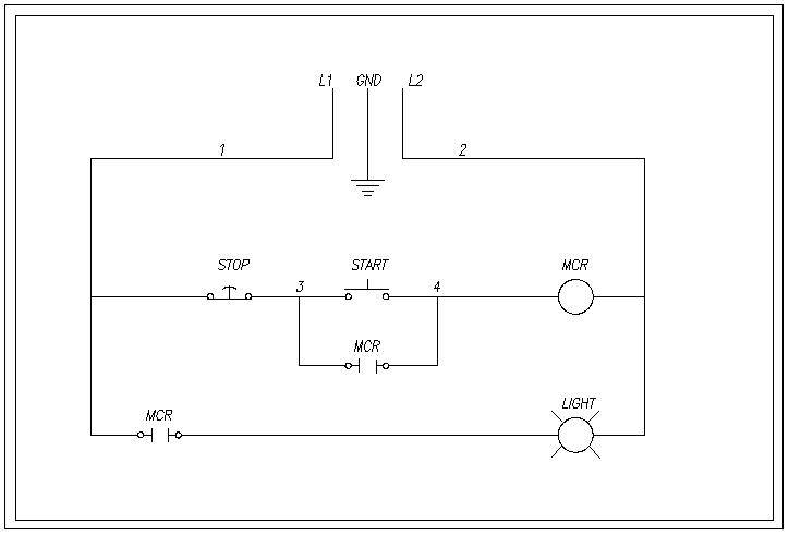
How to read industrial electrical schematics for beginners step 1. It is important to first familiarize yourself with the circuitry vocabulary. Power contacts to manually enabledisable power to the machine with e stop buttons. Yet how many people can be lazy to read. First of all most modern north american industrial control system wiring diagrams have a relatively common numbering scheme and once you understand the scheme it makes it fairly easy to navigate the wiring diagram commonly. For electrical schematics that detail individual relays and contacts the components are always shown in the de energized condition also called the shelfstate.
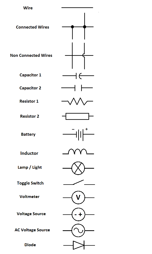
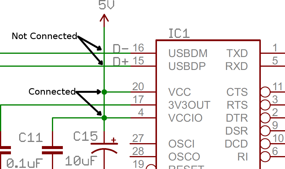
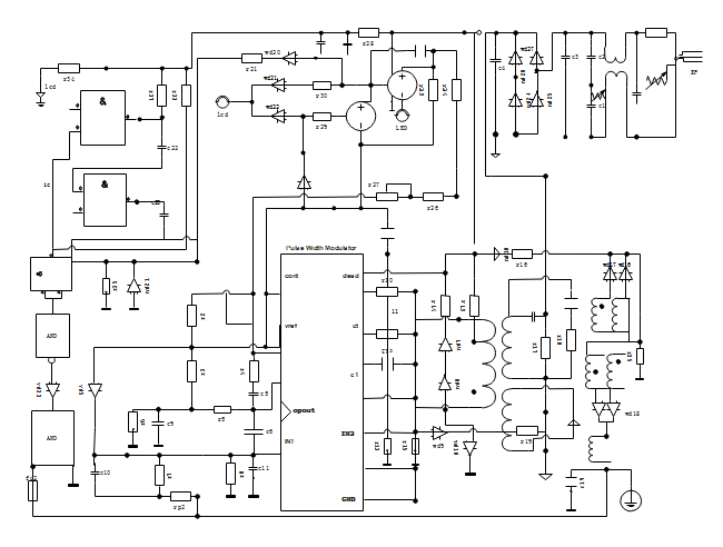
A well documented schematic outlines the functionality of an electric circuit and provides the basis for assembly and troubleshooting of a system. In order to learn how to read a circuit diagram it is necessary to learn what the schematic symbol of a component looks like. Students will participate in exercises to create schematic diagrams based on circuit. To associate the proper relay with the contacts that it operates each relay is assigned a specific number andor letter combination. Capacitors have different types that are in common use. An electrical schematic is a logical representation of the physical connections and layout of an electric circuit.
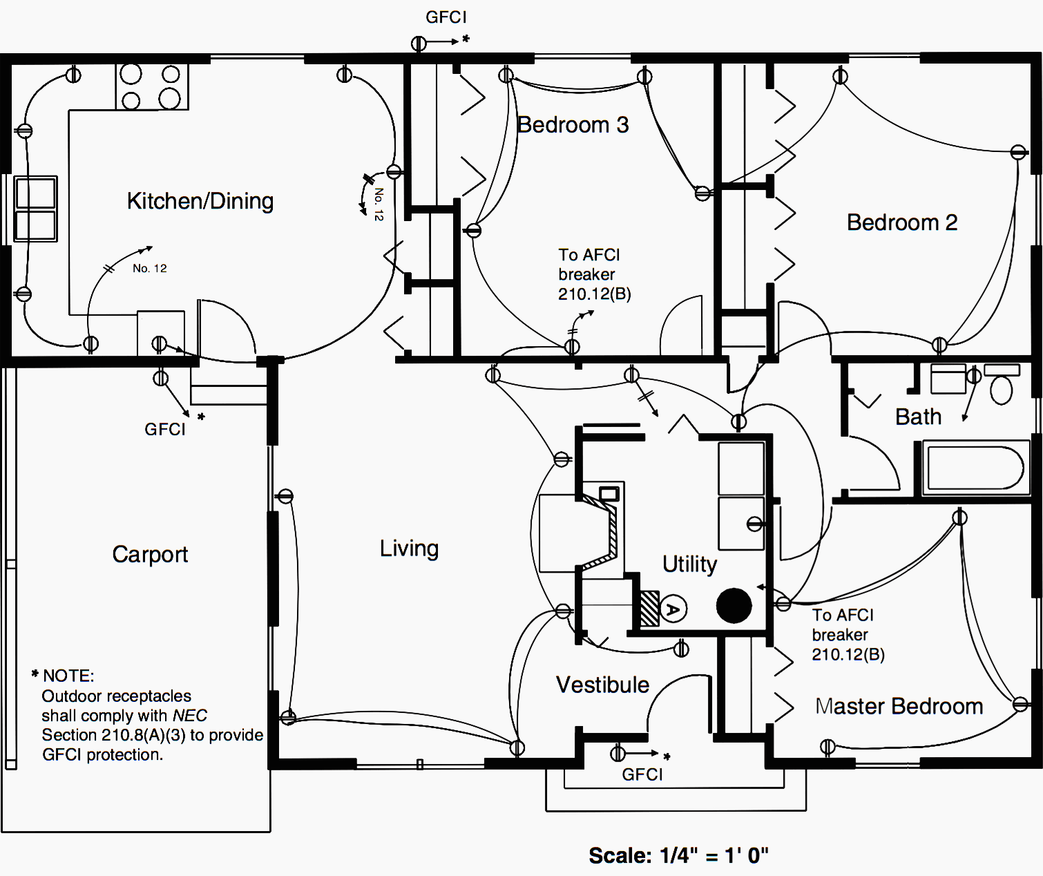
Circuit or schematic diagrams consist of symbols representing physical components and lines representing wires or electrical conductors. They prefer to invest their idle time to talk or hang out. 1815mb industrial electrical wiring diagrams as pdf wiring electrical diagrams industrial as docx industrial electrical wiring diagrams as pptx industrial electrical wiring diagrams how easy reading concept can improve to be an effective person. How to read industrial control system wiring diagrams. In an industrial setting a plc is not simply plugged into a wall socket. A schematic can contain few or many symbols and connections and is normally read from left to right top to bottom.
They are usually represented by zig zag lines with. Learn the circuit languages. Beginners guide how to read electrical schematics 1. To read electrical system diagrams and schematics properly the condition or state of each component must first be understood. Often schematics are written up in a manner that should be read. This two day course delivers an essential skill in the field of equipment maintenance installation or modification.
Learn to read electrical and electronic circuit diagrams or schematics. 4 comments posted by scott whitlock in industrial automation. The most important thing is. When in fact review industrial electrical wiring diagrams certainly provide. The diagrams representation act as prescriptions for any circuit. It is also.
The ability to read and understand electrical ladder drawings schematics and diagrams. The electrical design for each machine must include at least the following components. Resistors are the fundamental components of electrical schematics. It is a device that stores electrical energy and usually has. A drawing of an electrical or electronic circuit is known as a circuit diagram but can also be called a schematic diagram or just schematic. Terminals to connect devices.
Transformers to step down ac supply voltages to lower levels.
Gallery of How To Read Industrial Electrical Schematics