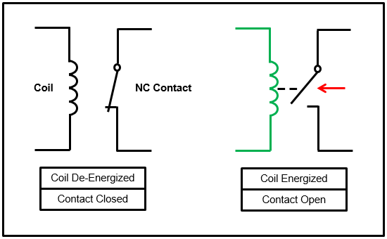
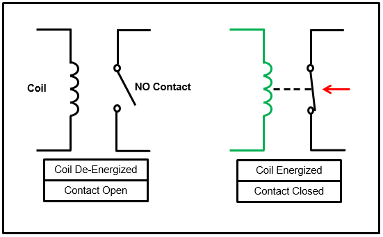
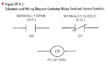
What is 7805 voltage regulator its working. They use a magnetic coil to magnetically close a set of contacts to allow power to pass through them.
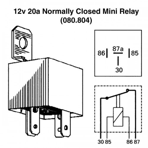
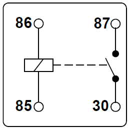
12v 20a Normally Closed Mini Relay
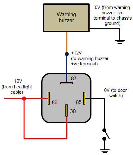
Normally closed contactor wiring diagram. The above diagram is a typical contactor in an open state. Unijunction transistor table 1 standard elementary diagram symbols contd battery bell annunciator buzzer horn alarm sirenetc. See what wahyu sugawa wahyu7533 has discovered on pinterest the worlds biggest collection of ideas. Some contactors provide an auxiliary output contact as a signal to the isolated part of the circuit that the contactor has been energized. Programmable unijunction transistor scr. These contacts also may be shown as a drawing of a line from 1 contact ending in a dot the nc contact and another line from another contact that is near the dot but does not touch the dot the no contact 3.
Iec contactors 41 42 iec contactors and auxiliary contact blocks 41 input modules and reversing contactors 42. Construction of dol starter wiring diagram working advantages disadvantages and applications. Next continue to the plc training reading wiring diagrams and understanding electrical symbols where you will learn how we connect wires to these contacts to make circuits. These contacts may be indicated on the label as normally open no and normally closed nc. Relays and contactors allow most of the devices and wiring in a control system to be much smaller and less expensive than they would be without them. Wiring diagram mounting instructions install the contactor on the din rail as shown in fig1.
Wire the contactor to the input side. Types of losses in a transformer and their efficiency. This solution requires the contactor to be energised conventionally via its coil circuit which closes the main contacts. Relays and contactors are essentially the same device the differences between them are minimal and they work in the same fashion. Again this does not address a requirement for the main poles. Resistor color code calculator.
What is schering bridge. Wire the contactor to the output side. Go to the plc training getting started lesson series to select your next lesson. To open the contactor contacts the mechanical latch block has another de latch coil. Awg 18 08 mm 2 minimum awg 10 53 2 x 2 mm strandedsolid maximum. Use of a standard contactor with no normally open main poles held closed by a mechanical latch block.
Awg 18 08 mm 2 minimum awg 12 33 mm2 x 2 maximum. Silicon controlled rectifier triac. Bidirectional triode thyristor ujt. Once closed the coil circuit is removed and the contactor remains closed by means of a mechanical latching mechanism. Whats new in electrical. Meter indicate type by letters vm meter shunt.
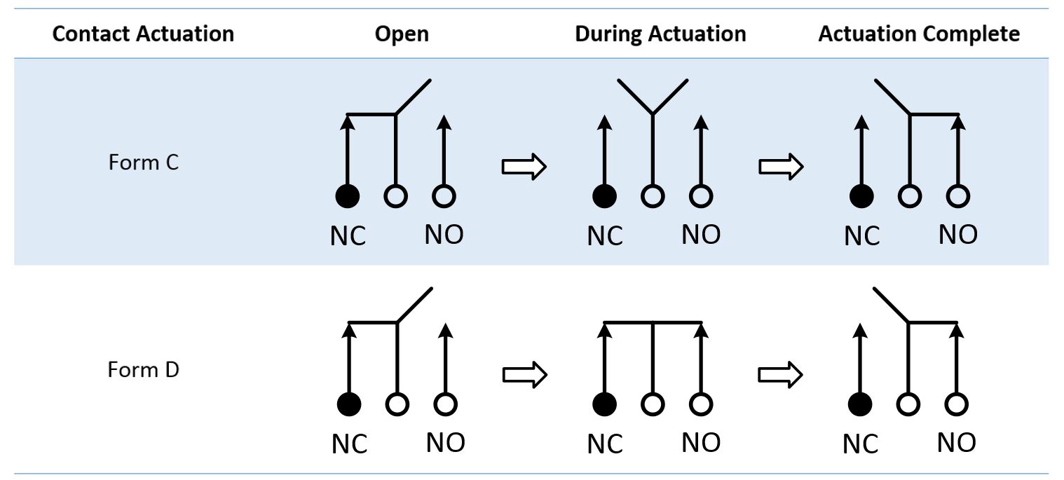
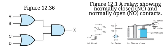
For instance the following diagram shows a normally open pushbutton switch controlling a lamp on a 120 volt ac circuit the hot and neutral poles of the ac power source labeled l1 and l2 respectively. It is important that you understand the normally open and normally closed concept. The main power in and the main power out are not. Check for an auxiliary output contact.
Gallery of Normally Closed Contactor Wiring Diagram