A single phase motor starter wiring diagram is shown in the below figure. Here is a single loop of a copper wire of 01 with 200 turns.

Braking Of Single Phase Induction Motor Plugging And Reversal
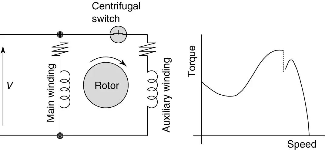
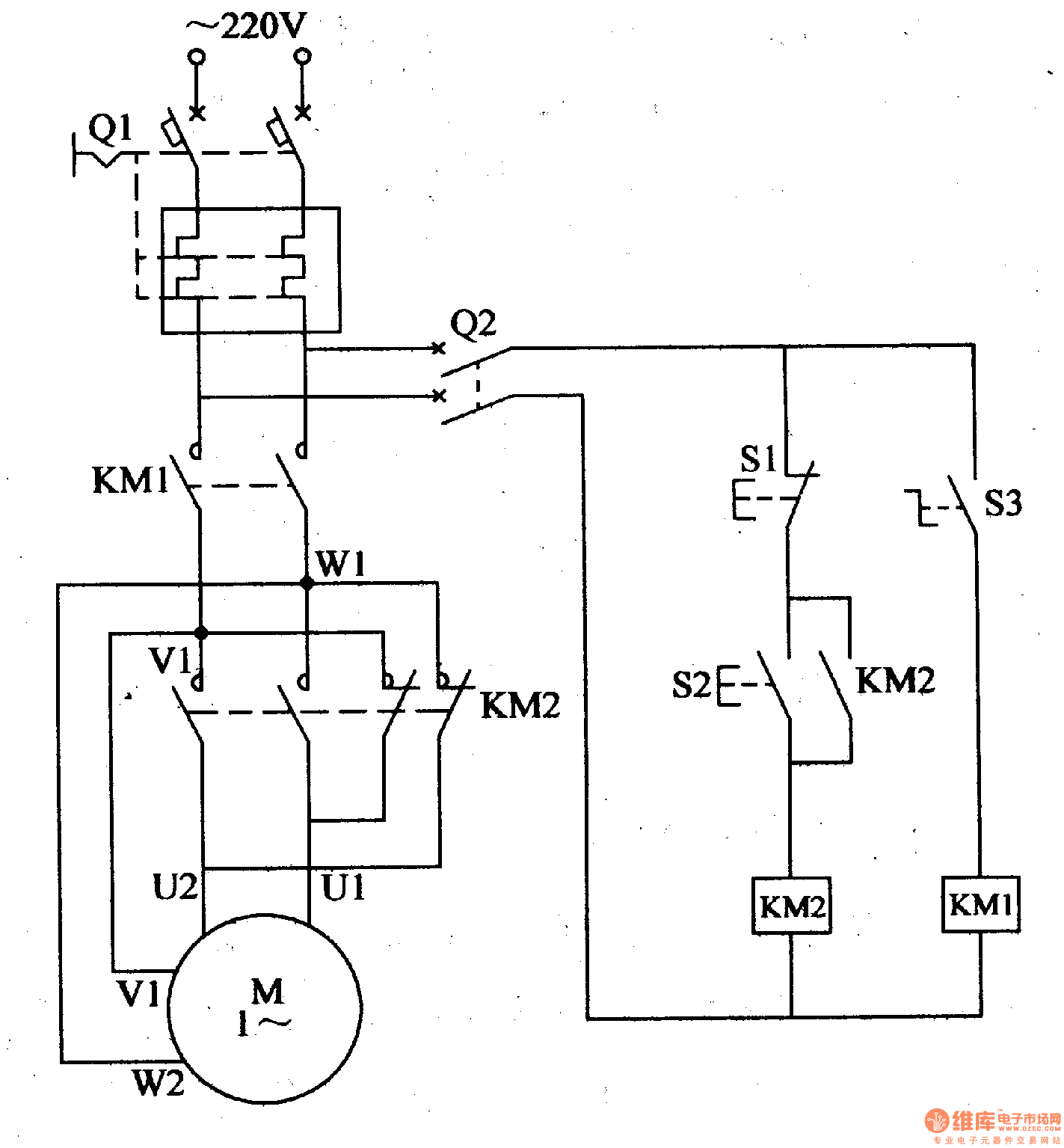
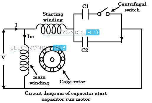
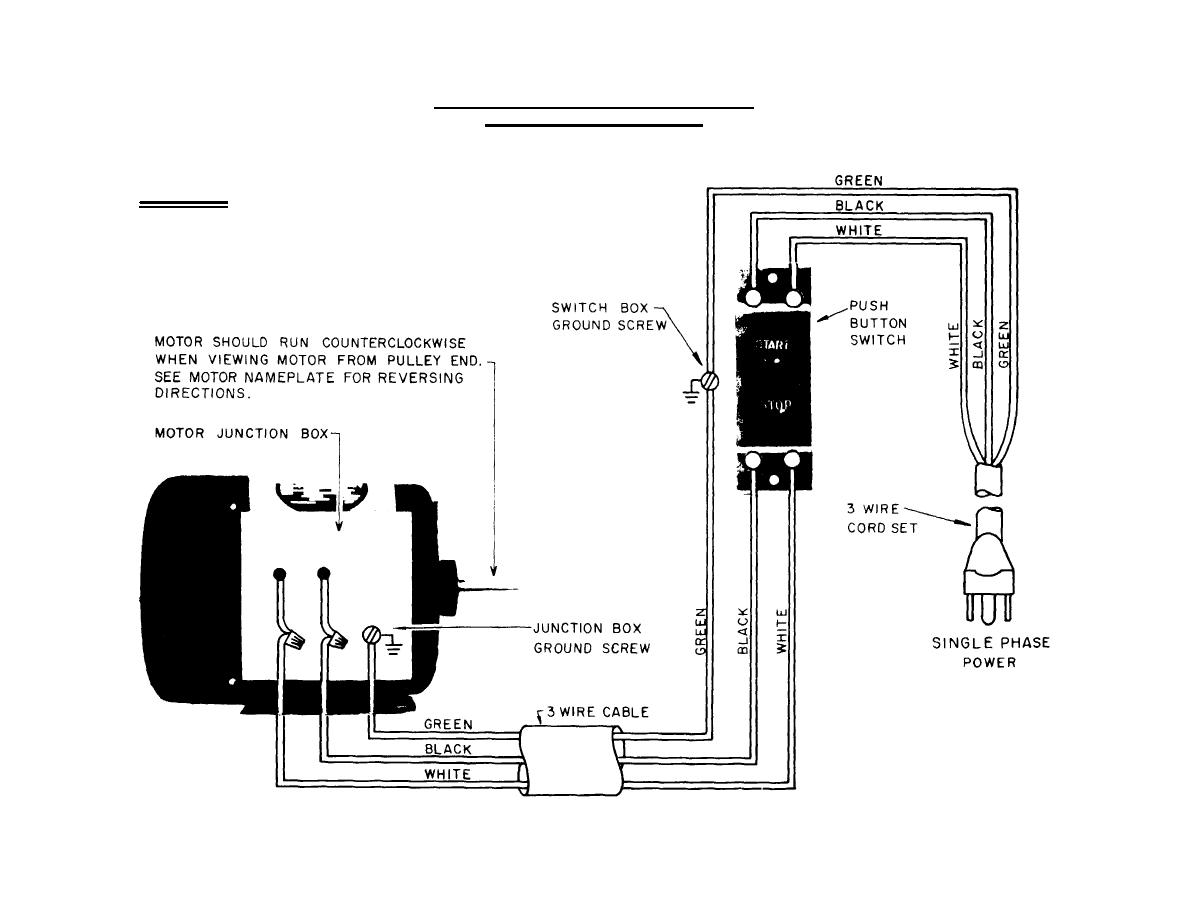
Single phase motor circuit diagram. It is intended to help all the typical user in building a correct program. It is important to point out from the phasor diagram that the phase difference between im and is is almost 80 degrees as against 30 degrees in a split phase induction motor. In the above one phase motor wiring i first connect a 2 pole circuit breaker and after that i connect the supply to motor starter and then i do cont actor coil wiring with normally close push button switch and normally open push button switch and in last i do connection between capacitor start motor and contactor. It is evident from the phasor diagram that the current through the starter winding is leads the voltage v by a small angle and the current through the main winding im lags the applied voltage. The above diagram is a complete method of single phase motor wiring with circuit breaker and contactor. These instructions will probably be easy to comprehend and implement.
With this particular manual you may be able to see how each element should be connected as well as the actual actions you need to take in order to effectively complete a. It reveals the components of the circuit as simplified shapes as well as the power and also signal connections in between the tools. Variety of 240v motor wiring diagram single phase. Thus a capacitor start induction run motor produces a better rotating magnetic field than the split phase motors. It is to be. This motor runs on ac current the rotating magnetic field.
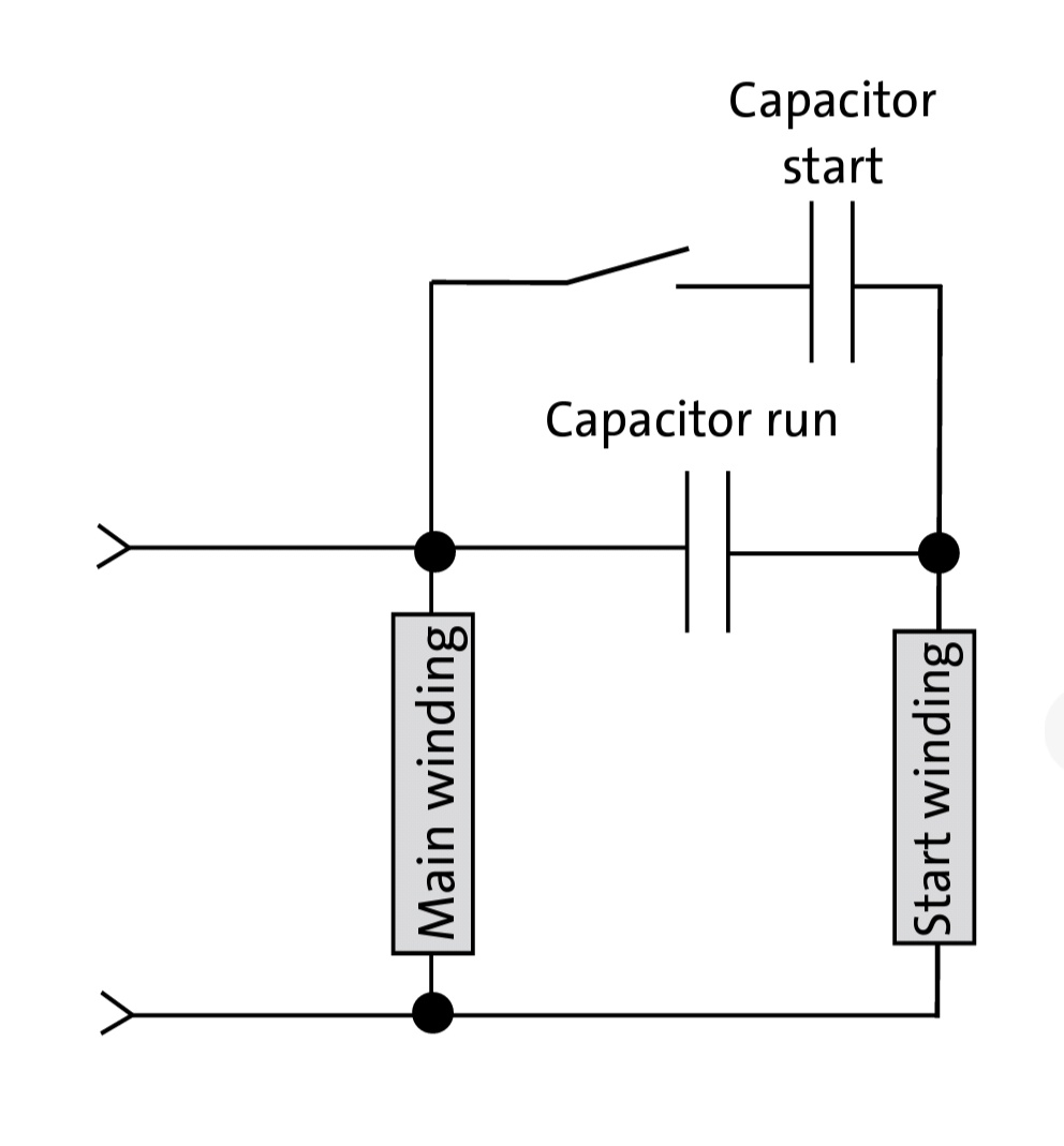
Soft start of induction motor by acpwm in this drive the load is connected in series with the input terminals of the bridge rectifier and its output terminals are connected to the pwm controlled power mosfet igbt or bipolar or power transistor. Types of single phase induction motors electrical a2z single phase induction motors are traditionally used in residential applications such as ceiling fans air conditioners washing machines and refrigerators single phase motor wiring with contactor diagram the plete guide of single phase motor wiring with circuit breaker and contactor diagram. And a rotating stator with a ring mangnet moving freely on the armature. Wiring diagram will come with numerous easy to follow wiring diagram directions. Single phase motor wiring diagram with capacitor start. A wiring diagram is a streamlined conventional pictorial depiction of an electric circuit.
240 vac motor wiring wiring diagrams hubs single phase motor wiring diagram with capacitor.
Gallery of Single Phase Motor Circuit Diagram